


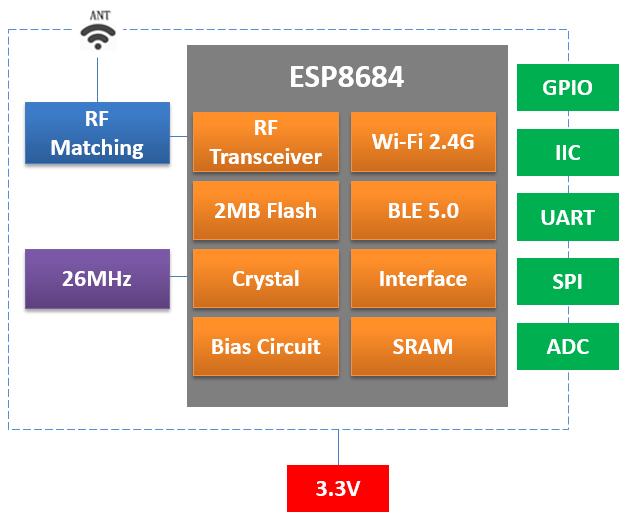
The DOIT ESPC2 family offers several physical formats around the ESP32-C2 / ESP8684 platform. The supplied manuals describe 2.4 GHz Wi-Fi 802.11 b/g/n, Bluetooth LE, 576 KB ROM and 272 KB SRAM. The main selection differences are the package, exposed signals, flash option and antenna connection.
Nine formats to review
| Module | Stated module dimensions | Antenna arrangement |
|---|---|---|
| ESPC2-01 / ESPC2-01E | 14.5 × 24.5 mm | PCB / U.FL respectively |
| ESPC2-02 | 15 × 17.3 × 3 mm | PCB |
| ESPC2-05 | 15 × 20 × 3 mm | PCB |
| ESPC2-12 / ESPC2-12E | 16 × 24 × 3 mm | PCB / external U.FL respectively |
| ESPC2-20 / ESPC2-20E | 18 × 20 × 3 mm | PCB / external U.FL respectively |
| ESPC2-M1 | 12.3 × 20 × 3 mm | PCB |
The external antenna connection for ESPC2-12E and ESPC2-20E is described in their antenna-connector sections. Check those sections together with the physical drawing when preparing the board. This is particularly useful where a general parameter table contains a repeated antenna description.
Choose flash by the ordering code
ESPC2-01, ESPC2-01E, ESPC2-02 and ESPC2-05 list 2 MB flash. The ESPC2-12, ESPC2-12E, ESPC2-20, ESPC2-20E and ESPC2-M1 ordering tables list N2 and N4 variants with 16 Mbit and 32 Mbit flash. Those values convert to 2 MB and 4 MB. Keeping bits and bytes distinct prevents an eightfold mistake in the storage budget.
For a connected sensor, reserve flash for the application, network configuration and any update partitions. For a product that stores local records, define the retention requirement before choosing the memory variant. The size of the firmware image alone is not the complete storage requirement.
Allocate pins before selecting the smallest board
The manuals list different exposed GPIO counts across the packages: five for the ESPC2-01 formats, eight for ESPC2-02, eleven for ESPC2-05, thirteen for the ESPC2-12 formats and ESPC2-M1, and fourteen for the ESPC2-20 formats. Read these as feature-list counts. The usable combination depends on multiplexing, boot requirements and the exact functions assigned to each pin.
A lighting controller may need PWM, an input button and an indicator, while a sensor gateway may need I²C plus a UART for programming or diagnostics. Map these requirements to the pin table before reducing the module footprint. Leave a practical route for firmware loading and recovery during production.
Bring up the radio on a stable supply
The manuals describe a typical 3.3 V supply and 3.0–3.6 V operating range. Several also warn of substantial current demand during startup and RF calibration. Validate the supply response during those events rather than selecting a regulator from a sleep-current figure.
The C2 Wi-Fi feature lists specify 20 MHz bandwidth and a maximum stated PHY rate of 72.2 Mbps. That is a radio-link capability rather than an application throughput guarantee. Packet size, network conditions, firmware and power-saving settings determine the performance seen by a finished product.
Select the ESPC2 format by completing three checks together: the required pin allocation, the firmware storage budget and the antenna space inside the actual enclosure. This produces a more useful shortlist than comparing module area alone.
Source: Supplied DOIT user manuals for the models discussed.
Leave a Reply
You must be logged in to post a comment.