


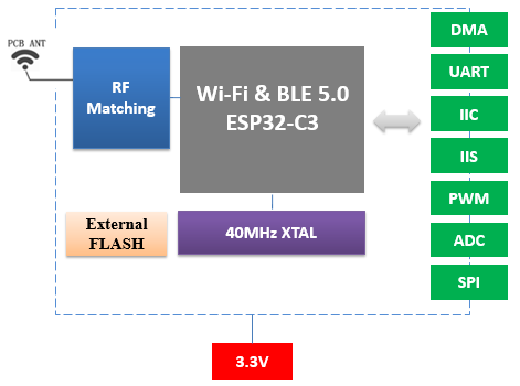
A shared chip family does not make every wireless module interchangeable. DOIT’s ESPC3 manuals cover seven module formats with different footprints, antenna arrangements and exposed interfaces. Each is intended for 2.4 GHz Wi-Fi and Bluetooth LE designs, but choosing the right version requires a closer look at the complete module.
Compare the available formats
| Module | Antenna | Documented selection detail |
|---|---|---|
| ESPC3-02 | PCB | 15 × 17.3 × 3 mm; ESP8685H2 / H4 listed |
| ESPC3-05 | PCB | 16 × 20 × 3 mm; ESP32-C3FH4 and 32 Mbit flash |
| ESPC3-12 | PCB | 16 × 24 × 3 mm; N2 / N4 / N8 flash options |
| ESPC3-12E | U.FL / IPEX | 16 × 24 × 3 mm; N2 / N4 / N8 flash options |
| ESPC3-20 | PCB | 18 × 20 × 3 mm; N2 / N4 / N8 flash options |
| ESPC3-20E | U.FL / IPEX | N2 / N4 / N8 options; confirm mechanical dimensions |
| ESPC3-32 | PCB | 18 × 25.5 × 3 mm; 4 MB flash listed as default |
The ESPC3-20E manual gives different dimensions in its feature list and parameter table. Confirm its mechanical drawing and sample measurements before releasing the host PCB. Likewise, the ESPC3-02 ordering table repeats a flash value for two suffixes; specify the required capacity explicitly rather than inferring it from that row.
Use the interface budget to narrow the choice
The ESPC3-02 feature list states eight GPIOs, while the other supplied C3 feature lists state fifteen. UART, I²C, SPI, PWM and ADC appear across the family. These functions share pins, and the final allocation must respect the selected module’s pin definition and startup behavior.
For a compact sensor, write down the bus, interrupt, power-control and indicator signals before choosing a footprint. For a lighting or control product, reserve the necessary PWM or output channels and confirm their startup states. Include access for programming and diagnostics so that a physically compact design remains practical to assemble and support.
Interpret radio and memory figures correctly
The manuals list 384 KB ROM, 400 KB SRAM and Wi-Fi 802.11 b/g/n. Their Wi-Fi feature lists include 20 MHz and 40 MHz bandwidth and a maximum stated PHY rate of 150 Mbps. Application throughput will depend on network conditions, packet handling and firmware behavior. It should be measured with the product’s real traffic.
For the models with N2, N4 and N8 options, the ordering tables identify 16, 32 and 64 Mbit flash, equivalent to 2, 4 and 8 MB. Include configuration data and the intended update strategy in that capacity decision. More flash does not change the internal SRAM available to the running application.
Validate the assembled product
PCB-antenna versions need clearance around the antenna area, while external-antenna versions need a defined cable and radiator arrangement. Evaluate wireless behavior after installing the enclosure, cables and nearby electronics. A test on an exposed development board does not reproduce the final RF environment.
The manuals describe UART download mode using the relevant boot configuration, including IO9 in the supplied C3 pin tables. Follow the complete boot and reset circuit for the chosen version. Combine this with power-rail measurements during startup, connection attempts and sustained transmission before approving the design for production.
Source: Supplied DOIT user manuals for the models discussed.
Leave a Reply
You must be logged in to post a comment.