


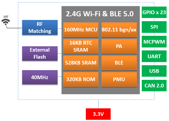
ESPC6-32 and ESPC6-32E bring 2.4 GHz Wi-Fi 6, Bluetooth LE and IEEE 802.15.4 into the DOIT ESP32-C6 module family. The supplied manuals describe a 160 MHz single-core RISC-V processor, 512 KB high-performance SRAM and 16 KB low-power SRAM. The two versions mainly offer different antenna arrangements for the host product.
Compare antenna and flash options
| Feature | ESPC6-32 | ESPC6-32E |
|---|---|---|
| Antenna | PCB antenna | IPEX external antenna connection |
| Dimensions listed | 18 × 25.5 × 3 mm | 18 × 25.5 × 3 mm |
| N4 flash option | 4 MB | 4 MB |
| N8 flash option | 8 MB | 8 MB |
| N16 flash option | 16 MB | 16 MB |
| Wi-Fi band | 2.4 GHz | 2.4 GHz |
The flash capacities above convert the manual’s 32, 64 and 128 Mbit entries to megabytes. Include application images, persistent data and the intended update partitions when choosing a variant. The ordering tables do not list a PSRAM option for these modules.
Wi-Fi 6 does not imply a 5 GHz radio
The C6 manuals specify IEEE 802.11 b/g/n/ax operation in the 2.4 GHz band. A requirement for 5 GHz connectivity therefore needs a different documented radio configuration, such as the dual-band ESPC5 family. Identify the required frequency band explicitly in the product specification instead of using the Wi-Fi generation name alone.
For local device networking, the C6 manuals also list IEEE 802.15.4-2015, a 250 Kbps PHY rate, Thread 1.3 and Zigbee 3.0. These entries describe available platform capabilities. The application still needs the correct firmware, network roles and integration testing. They do not establish that a finished product is a certified hub or supports every ecosystem out of the box.
Plan the system’s radio behavior
Start by defining the main communication path. A device might use Wi-Fi for its normal network connection, or it might participate in an IEEE 802.15.4 network with firmware designed for that purpose. If Bluetooth is included in setup or maintenance, document when it is active and what data it exchanges.
Test the planned combination under realistic traffic. Commissioning, network recovery and firmware updates can produce different radio and memory demands from normal idle operation. A successful single-protocol demonstration is only one part of evaluating a multi-protocol product.
Review power, pin allocation and antenna placement
The manuals list interfaces including I²C, I²S, SPI, PWM, ADC and TWAI, with twenty-three GPIOs in the feature list. Use the complete pin table to check multiplexing and startup requirements. Reserve access to firmware download and diagnostics before allocating every signal to the application.
The electrical table lists a 3.0–3.6 V supply range with a typical 3.3 V value. The power section warns of startup peaks above 500 mA during RF calibration, so validate the supply with margin and measure the rail during startup. That transient behavior matters even when the application spends much of its time asleep.
Choose ESPC6-32 when the host board can provide the specified PCB-antenna clearance. Evaluate ESPC6-32E when the radiator needs a separate location. Confirm the mechanical drawing, connector arrangement and assembled RF performance before finalizing either choice.
Source: Supplied DOIT user manuals for the models discussed.
Leave a Reply
You must be logged in to post a comment.