


Description
Parameter information
Frequently Asked Questions
Q: What is the relationship between Doit Intelligence and Espressif Systems?
A: Espressif Systems supplies the chips used in ESP-series modules, while Doit Intelligence develops and manufactures ESP-series modules. Espressif Information Technology is a shareholder of Doit Intelligence. For further details, please refer to Tianyancha.
Q: What is the difference between the ESP8285 and ESP8266?
A: The ESP8285 integrates 1 MB of on-chip flash memory and is fully package- and protocol-compatible with the ESP8266. It offers a higher level of integration and better high-temperature performance. Conventional external flash memory is typically rated for temperatures up to 85°C.
Q: Which ESP8266 module should customers select?
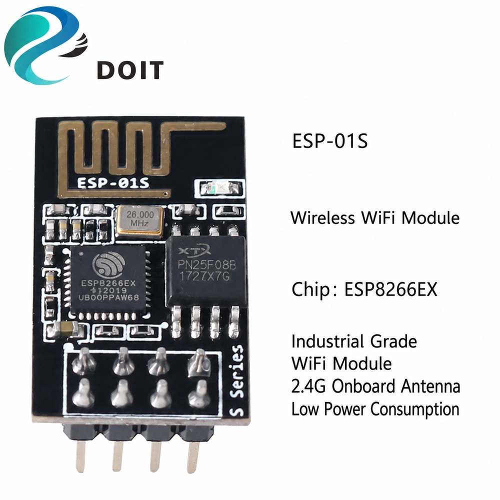
A: The ESP-F/F1 or ESP-M1/M2 is recommended. For through-hole applications, the ESP-01S is recommended.
Q: What are the differences between the ESP-F, ESP-12E, and ESP-12F?
A: The ESP-F uses a four-layer PCB, while the ESP-12E and ESP-12F use two-layer PCBs. If certification and higher quality are required, select the ESP-F, which supports FCC, CE, and SRRC certification requirements. Its four-layer PCB includes a ground-plane layer, providing more stable signal performance.
Q: What is the performance of the ESP-series modules?
A: ESP-series modules operate at clock frequencies from 80 to 160 MHz. The stated maximum UART transmission rate is 115200 × 40, or approximately 4.5 Mbps. ESP8266 modules support up to 16 MB of external flash memory. The ESP series has 160 KB of RAM, of which less than 50 KB is available to the user. The internal ADC has a 12-bit effective resolution, while the API returns 10-bit values.
Q: Which ESP-series module offers the longest transmission range?
A: The transmission range depends on the antenna. The approximate open-field ranges are:
- ESP-F/M/S: 150 m
- ESP-12F/12E: 100 m
- ESP-01/01S/07: 70 m
Q: Can both antennas on the ESP-07 be used simultaneously?
A: They can be used simultaneously, but this is not recommended because antenna efficiency will be significantly reduced.
Q: What is the maximum packet size for TCP and UDP data transmission?
A: The maximum single-packet payload is 1,460 bytes for TCP and 1,472 bytes for UDP.
Q: Why are packets lost during transparent transmission?
A: Packet loss occurs because serial-port flow control has not been configured.
Product Description
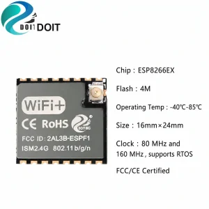
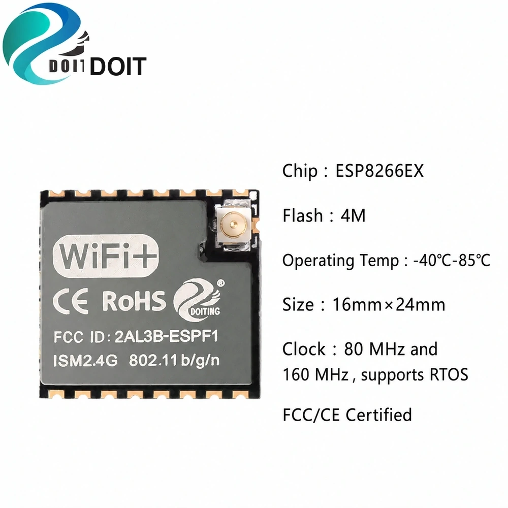
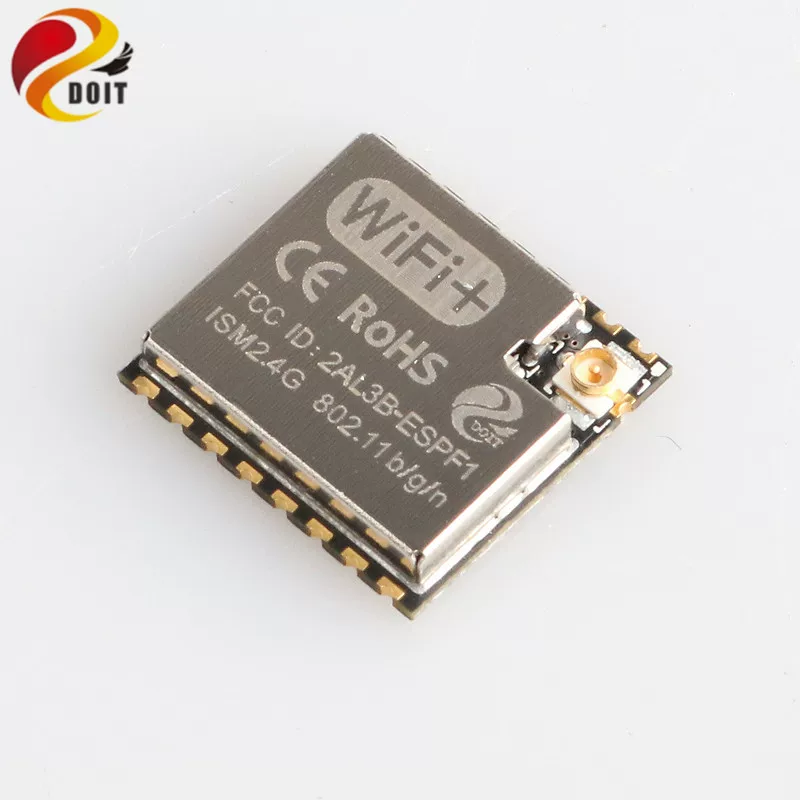
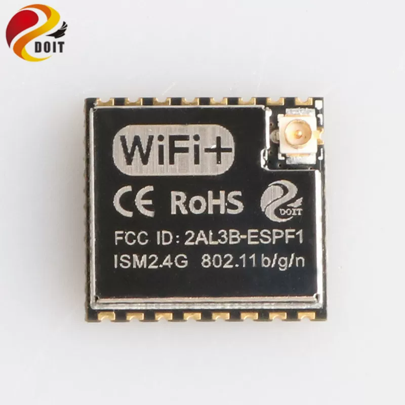
The ESP-F1 module is powered by the cost-effective ESP8266EX processor. In a compact package, the ESP8266EX integrates an industry-leading Tensilica L106 ultra-low-power 32-bit microcontroller with a 16-bit compressed instruction mode. It supports clock frequencies of 80 MHz and 160 MHz, as well as an RTOS.
The ESP8266EX provides complete Wi-Fi networking capabilities. It can operate independently or function as a slave device alongside an external host MCU. In standalone operation, it can boot directly from external flash memory. Its integrated high-speed cache helps improve system performance and optimize memory utilization.
The ESP8266EX can also function as a Wi-Fi adapter through SPI/SDIO or I²C/UART interfaces, allowing it to be incorporated into virtually any microcontroller-based design.
The ESP-F1 module supports the standard IEEE 802.11 b/g/n/e/i protocols and a complete TCP/IP protocol stack. It can add network connectivity to existing devices or be used to build a standalone network controller.
The ESP-F1 module delivers maximum functionality at minimal cost, providing flexible possibilities for integrating Wi-Fi connectivity into other systems.
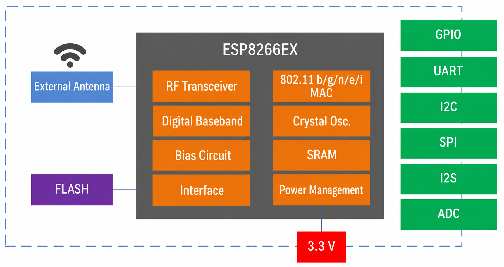
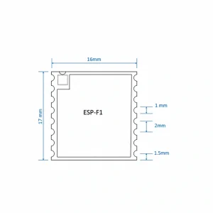
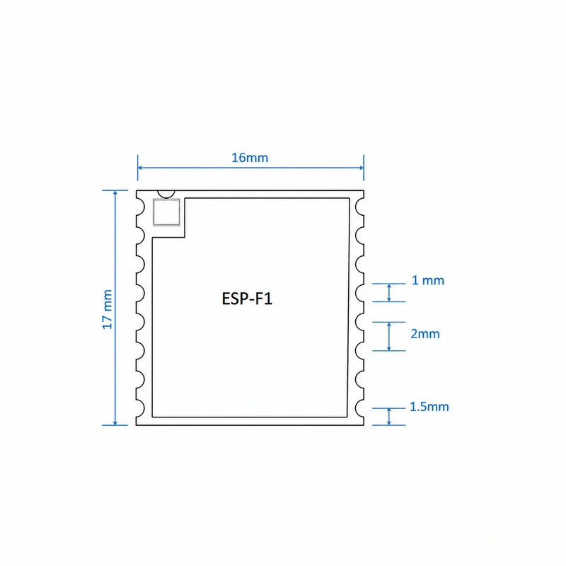
The main technical specifications of the module are as follows:
- Main Module Specifications
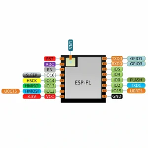
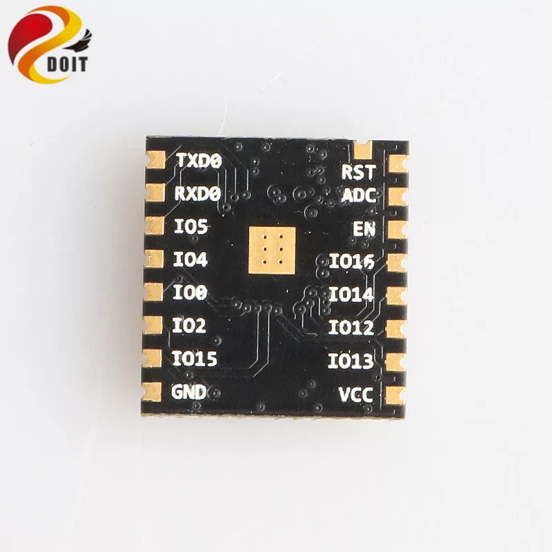
1.1 Pin Definitions
ESP-F
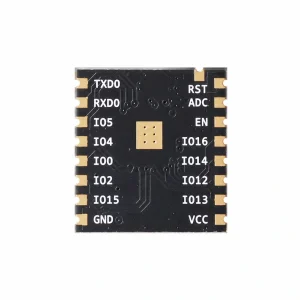
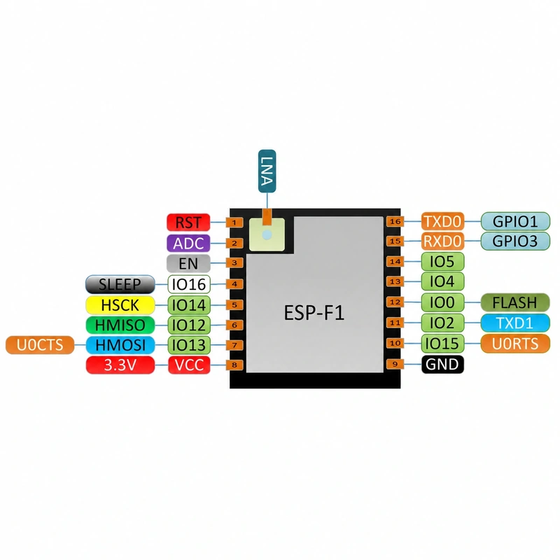
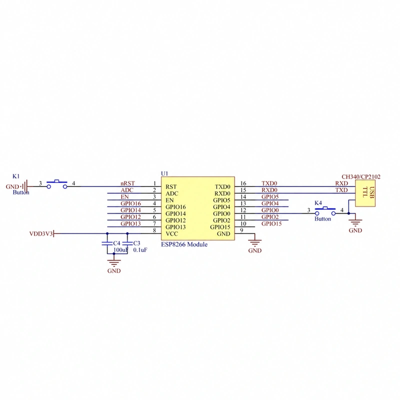
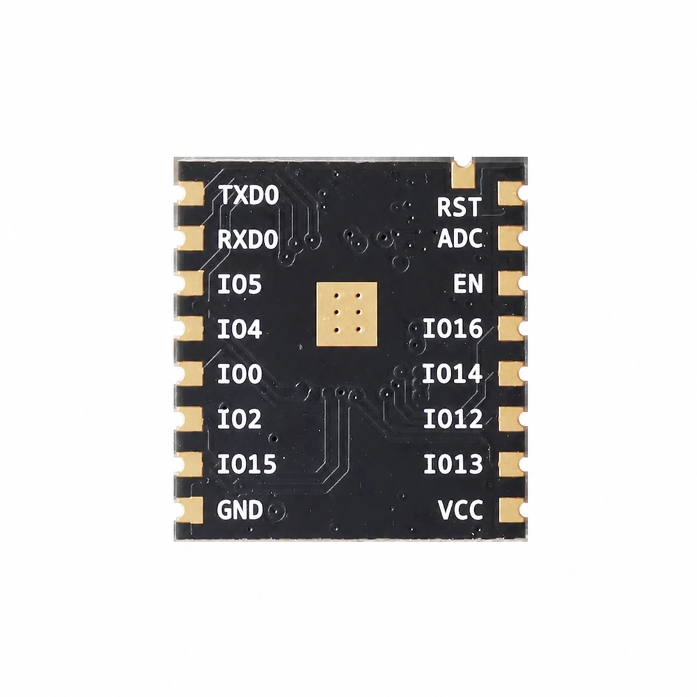
The pin definitions are shown in the following figure.


Notes:
- The module requires a 3.3 V DC power supply capable of delivering at least 500 mA.
- The maximum output current of the Wi-Fi module’s I/O is 12 mA.
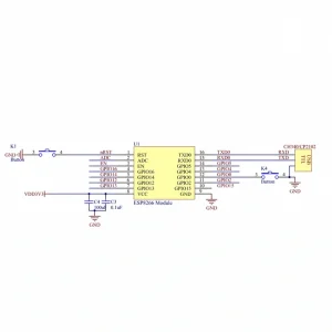
- The NRST pin is active low, while the EN pin is active high.
- To enter firmware upgrade mode, hold GPIO0 low and then reset or power-cycle the module. To enter normal operating mode, hold GPIO0 high and then reset or power-cycle the module.
- Connect the Wi-Fi module’s RXD pin to the external MCU’s TXD pin, and connect the module’s TXD pin to the external MCU’s RXD pin.
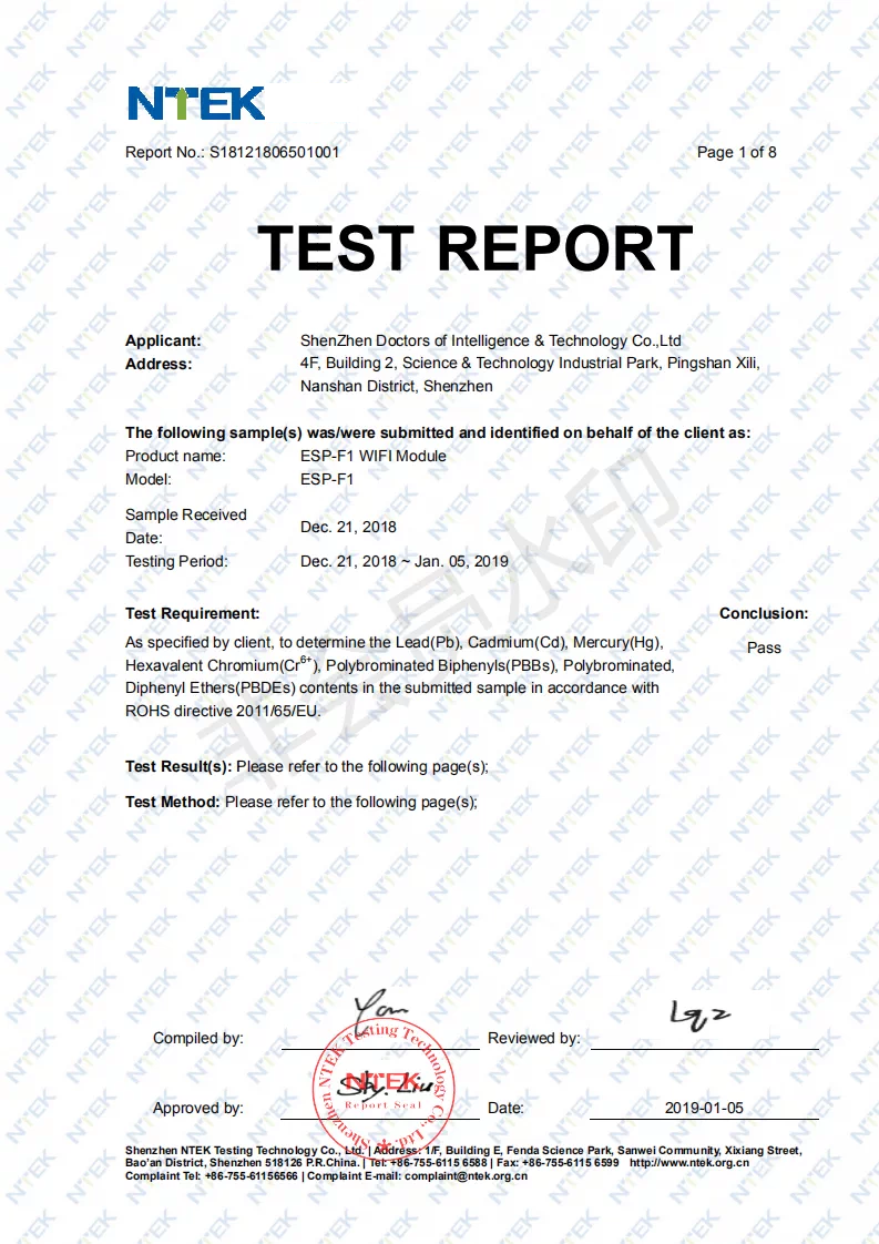
ESP-F1 Certifications:
Reviews
There are no reviews yet.