


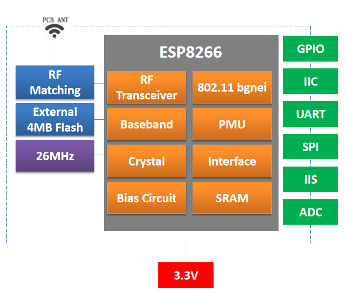
A small Wi-Fi controller still needs the right physical package, accessible signals and antenna arrangement. The DOIT ESP8266-family manuals cover everything from the compact ESP-01S interface to the ESP-12E and ESP-12F formats, plus smaller ESP-M modules. This guide compares the documented hardware choices for a product that needs 2.4 GHz Wi-Fi connectivity.
Start with the module format
| Module | Dimensions stated in the manual | Antenna | Selection focus |
|---|---|---|---|
| ESP-01S | 14.8 × 24.8 mm | PCB | UART integration with a small exposed interface |
| ESP-12E / ESP-12F | 16 × 24 × 3 mm | PCB | Broader access to peripheral signals |
| ESP-F | 16 × 24 × 3 mm | PCB | Check its own pin table and hardware revision |
| ESP-F1 | 16 × 17 × 3 mm | U.FL / IPEX | External antenna placement |
| ESP-M1 | 12.3 × 15 × 3 mm | U.FL / IPEX | Small module with a separate antenna |
| ESP-M2 | 12.3 × 20 × 3 mm | PCB | Narrow board layout |
| ESP-M3 | 15.7 × 20 × 3 mm | PCB | Compact interface with eight listed GPIOs |
These measurements describe the module, not the entire space required on the host board. A PCB antenna needs a clear surrounding area; an external antenna needs room for its connector, cable and radiator. Similar dimensions also do not establish pin compatibility. Match pad locations, supply pins and boot signals against the individual drawing before reusing a footprint.
Match interface access to the application
The ESP-01S manual lists one UART and four GPIOs. The ESP-12E and ESP-12F feature lists include eleven GPIOs and ADC, HSPI, I²C and I²S functions. These are multiplexed functions, so a peripheral list should not be read as a promise that every interface can operate on independent pins at the same time. Reserve the programming and boot-related signals before allocating sensors, LEDs or control outputs.
The manuals describe Station, SoftAP and combined Station-plus-SoftAP operation. A product can therefore be designed around joining an existing Wi-Fi network or exposing a local setup network, subject to its firmware. Serial transparent transmission, smart lighting and sensor networking are among the stated application areas. AT command support and over-the-air update behavior depend on the actual firmware supplied with the module.
Plan power and startup together
The ESP-12F manual specifies a typical 3.3 V operating point within a 2.8–3.6 V range, and notes peak operating current above 200 mA. Size the regulator and decoupling for radio activity, then measure the rail during startup and transmission. Use the voltage range in each selected module’s electrical table rather than applying one family-wide assumption.
For battery products, a quoted deep-sleep value describes a particular device state. The host regulator, indicators, sensors and wake circuitry add their own consumption. Measure the complete board across its real sampling, connection and sleep cycle before estimating battery life.
A practical selection workflow
- Choose the required signals and map their shared pin functions.
- Decide whether the enclosure can accommodate the PCB antenna keep-out.
- Check flash capacity, boot wiring and the supplied firmware for the exact orderable module.
- Validate Wi-Fi behavior inside the finished enclosure, including power cycling and recovery after a lost connection.
For a straightforward UART connection, begin by evaluating ESP-01S. For more peripheral access, compare ESP-12E and ESP-12F. When board width or antenna placement drives the design, examine ESP-F1 and the ESP-M formats against the mechanical constraints.
Source: Supplied DOIT user manuals for the models discussed.
Leave a Reply
You must be logged in to post a comment.